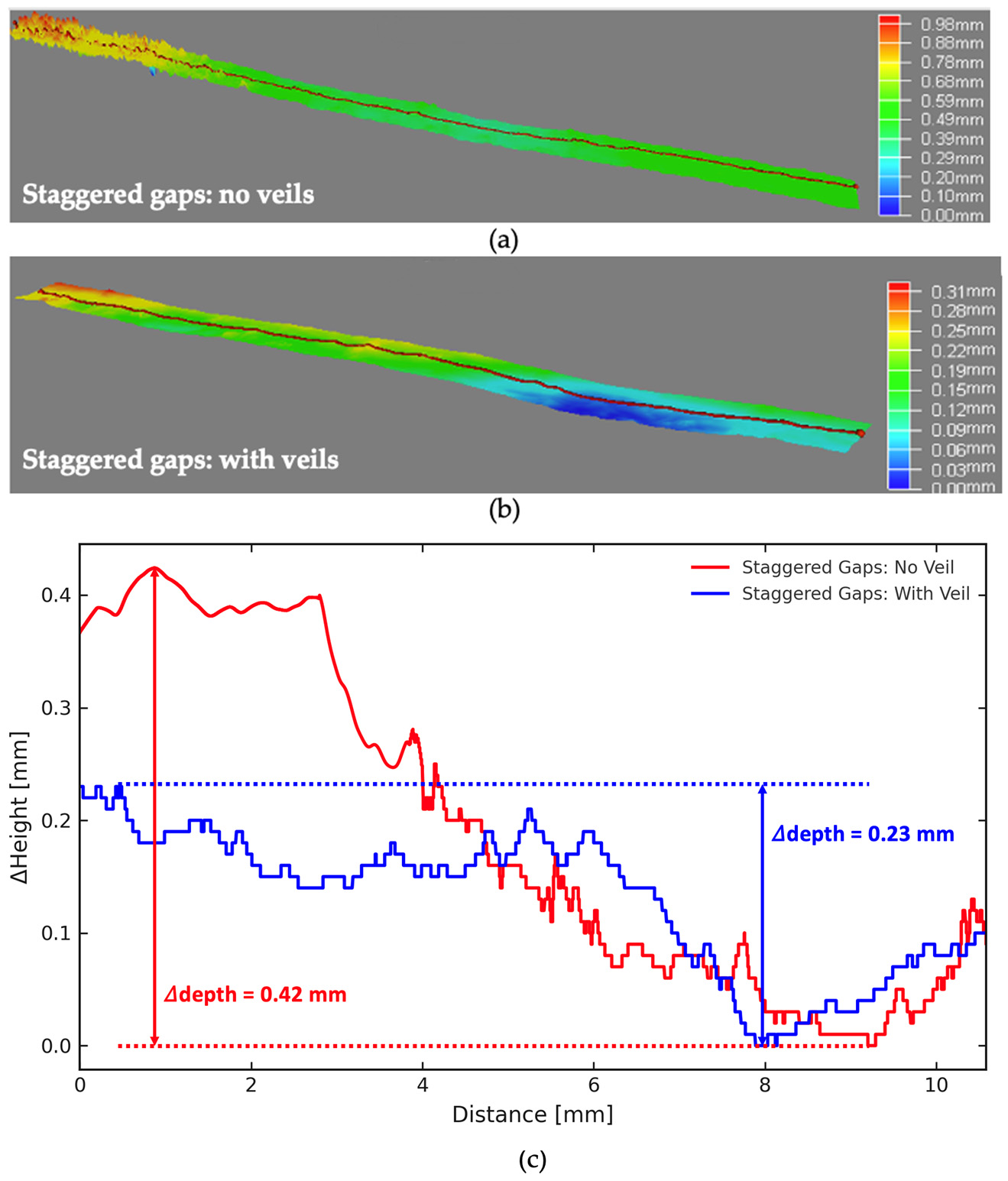
Peak-to-valley height variation was roughly halved by veil placement.
AFP composites
Mitigating out-of-plane fiber waviness in AFP laminates with tow-gaps
Selective PEI thermoplastic veil placement was used to control tow-gap morphology, reduce ply sinking, and stabilize damage evolution in cross-ply composite laminates.
Overview
Turning a tow-gap defect into a controlled morphology.
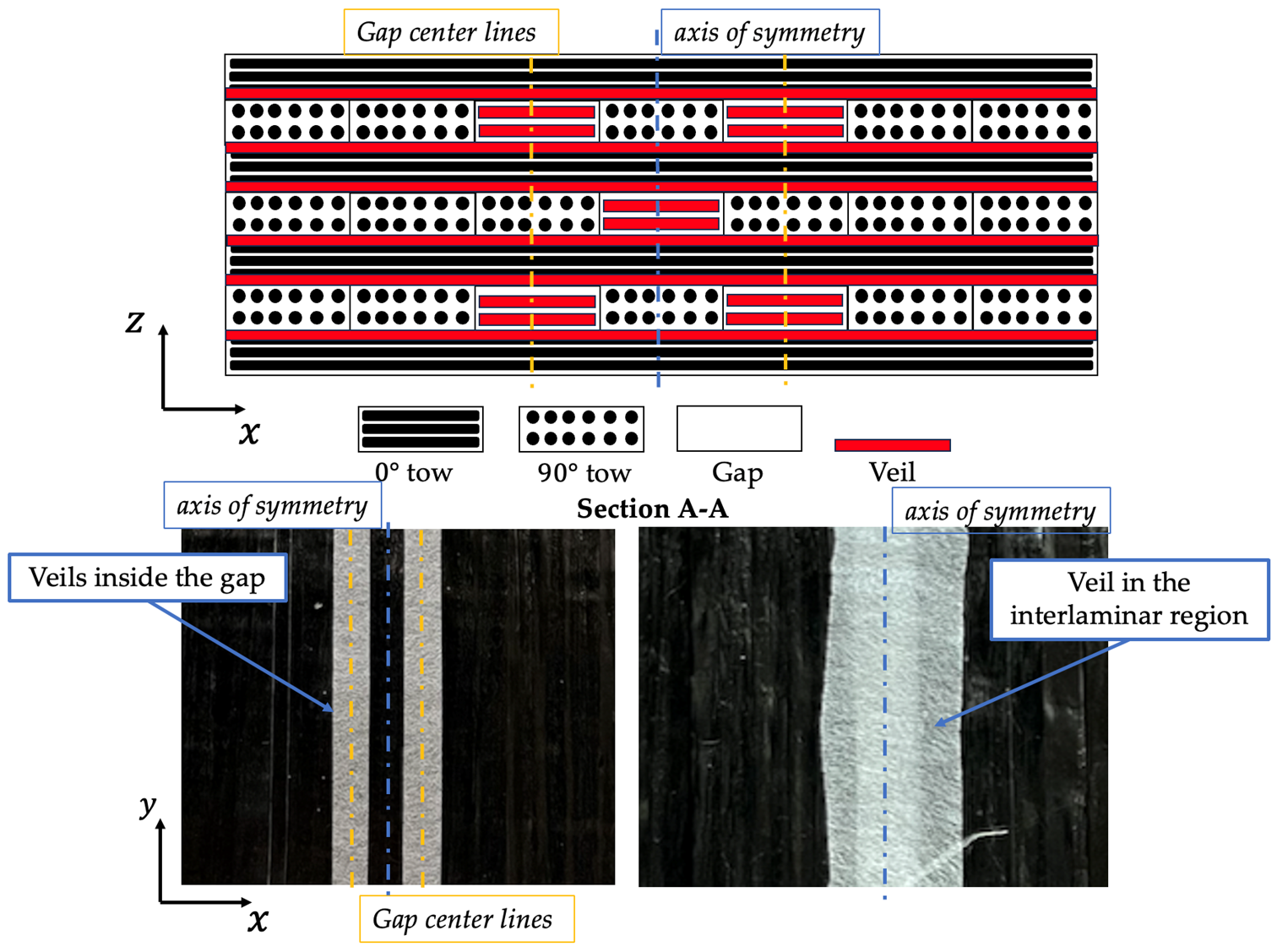
Fiber tow-gaps and overlaps from automated fiber placement can create resin-rich regions and local fiber waviness. During consolidation, deposited plies sink into gap regions, changing both external surface profile and internal load paths.
This study placed high-melting-temperature PEI thermoplastic veils directly into the tow-gaps. The veils preserved a more uniform laminate geometry and formed an interpenetrated network with the epoxy matrix, reducing resin-rich pockets while modifying failure behavior.
Main findings
Measured changes in morphology and response.
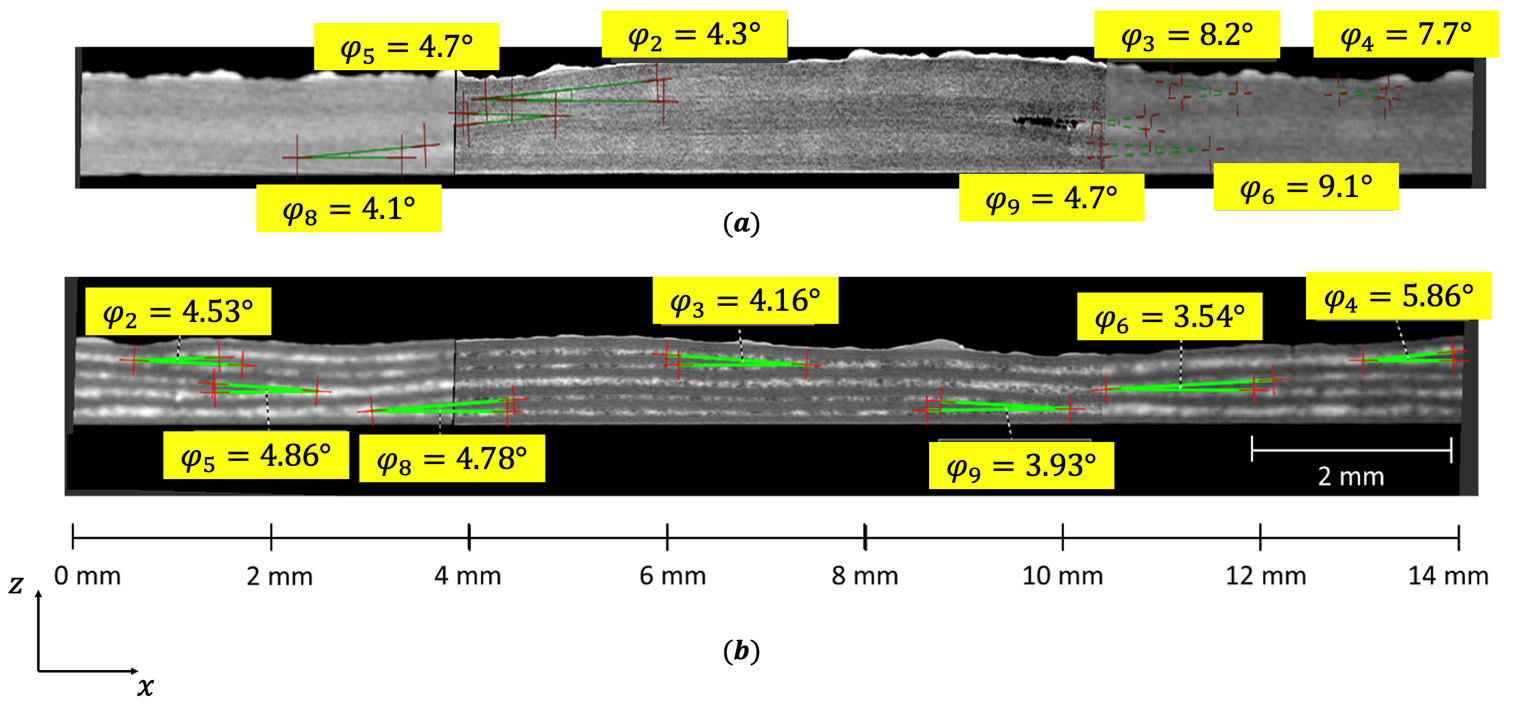
Microscopy and micro-CT showed smaller, less continuous resin-rich regions.
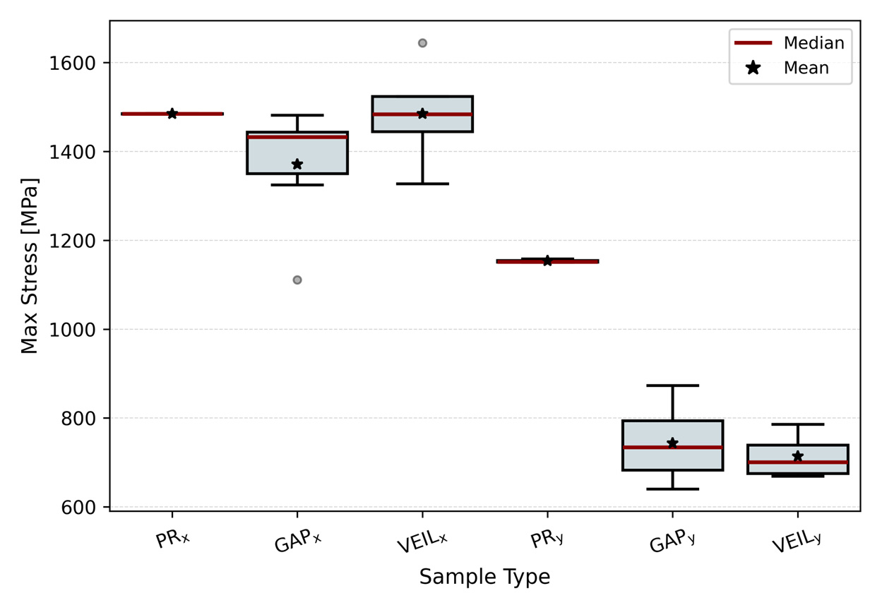
VEILx specimens recovered much of the strength lost in gap-only specimens.
Reduced waviness in load-bearing plies improved axial stiffness recovery.
Evidence
Figures extracted from the paper.
Workflow
Experiment and simulation tied to the same defect geometry.
- Fabrication
- Cross-ply laminates were built with controlled staggered tow-gaps and selective PEI veil insertion.
- Characterization
- Surface profilometry, optical microscopy, and micro-CT quantified waviness, resin-rich regions, and internal morphology.
- Testing
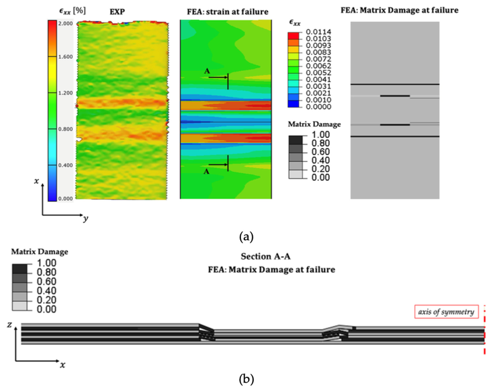
- Quasi-static tensile tests and full-field DIC captured stiffness, strength, and strain localization.
- Modeling
- Compaction-driven geometry was passed into progressive failure analysis to study matrix damage and delamination.
Takeaway
Veils work best as morphology-control scaffolds.
The strength recovery was strongest when veil placement suppressed waviness in the load-bearing plies. In the transverse direction, veils changed damage propagation but did not replace missing 90° reinforcement. This makes the method most useful when veil placement is aligned with critical load paths in AFP structures.